The PRS Research & Development Division developed software analysis for bulk carrier and tanker structure strength under the load cases defined in Common Structural Rules for Bulk Carriers and Common Structural Rules for Double Hull Oil Tankers. The Program supports surveyor’s work in calculating module zone strength using FEM for load cases automatically launched to the module.
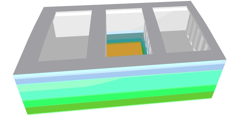
Sample load distribution calculated with the software for Alternate Load and Alt Block Load for the middle bulk carrier module is shown below.
 |
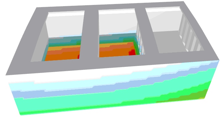 |
Fig. 1 Pressure distribution for Alternate Load – F2 and Alt-Block Load – H1
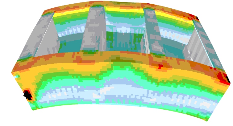
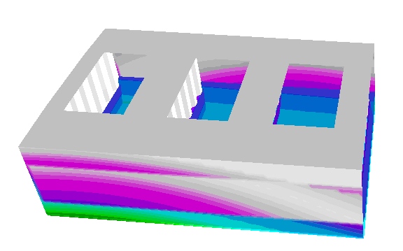
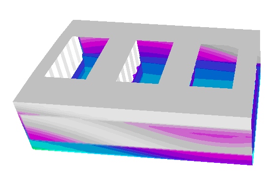
Load distribution allows for the analysis of stresses in the elements of the subject ship hull module. The figures below illustrate reduced stress distribution for the given loads and the extent of the structure deformations. (deformations multiplied 50 fold to the figure scale).
 |
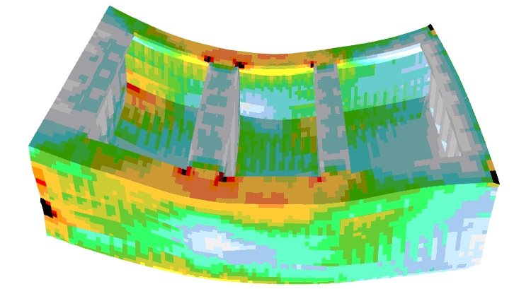 |
Fig. 2 Reduced stress distribution for Alternate Load – F2 (hogging) and Alt-Block Load – H1 (sagging)
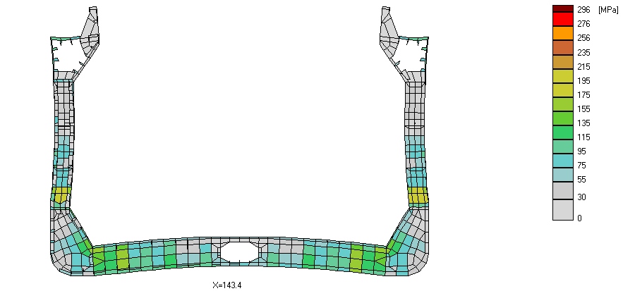
Fig. 3 Stress distribution in frame cross section
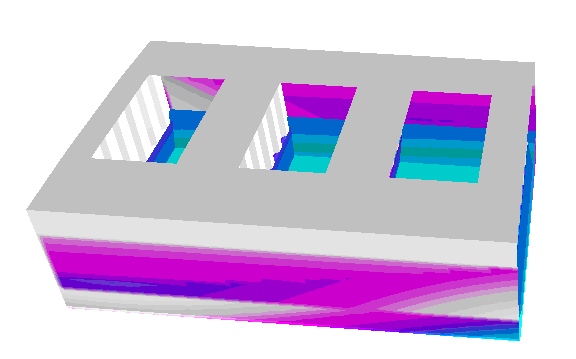
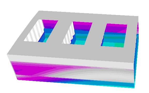
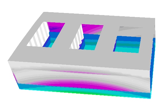
Developed procedures for automatic launch of loads to the finite element modelling of the hull module give a possibility for computing ship structure response to real ship structure loads in any waving conditions. These loads embrace, among others, the cargo gravitation generated loads and inertia related loads generated by ship motion in waves, wave generated loads on wetted ship surfaces, etc. Stress calculations are made in time domain. The figures below illustrate the wave pressure distribution changing in time, the structure displacement caused by the loads.
 |
 |
 |
 |
 |
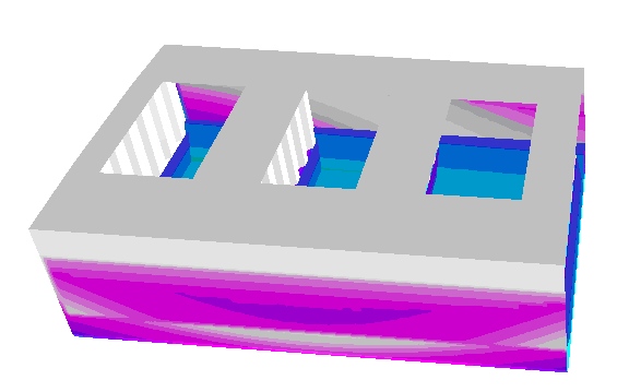 |
Fig. 4 Wave pressure distribution for t=0, t=1/5T,…., t=T
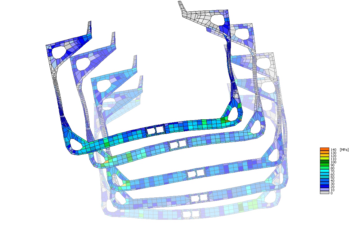
Fig. 5 Change in structure element displacement and stress distribution in frame cross section caused by structure module wave loads in time domain
The final software product serves to perform long-term predictions of ship behaviour in waves and an analysis of stresses for the ship’s life period. The so-called coefficient method was applied to predict stresses in the structure. The method involves division of hull structure into panels (bigger than finite elements), application of unit loads and calculation of the unit load impact on stress of structure elements examined.
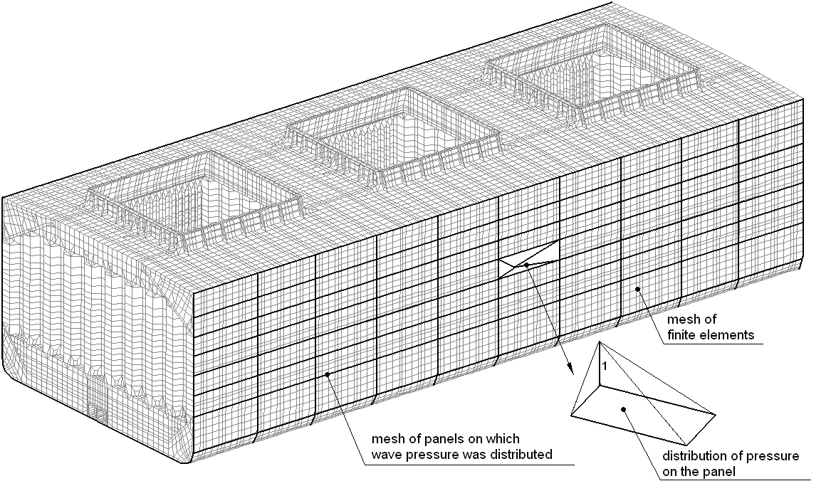
Fig. 6 Mesh of elements applied in the impact coefficient method
 |
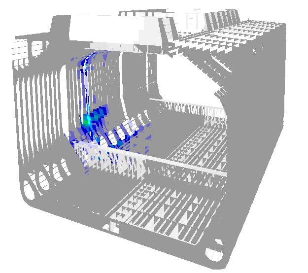 |
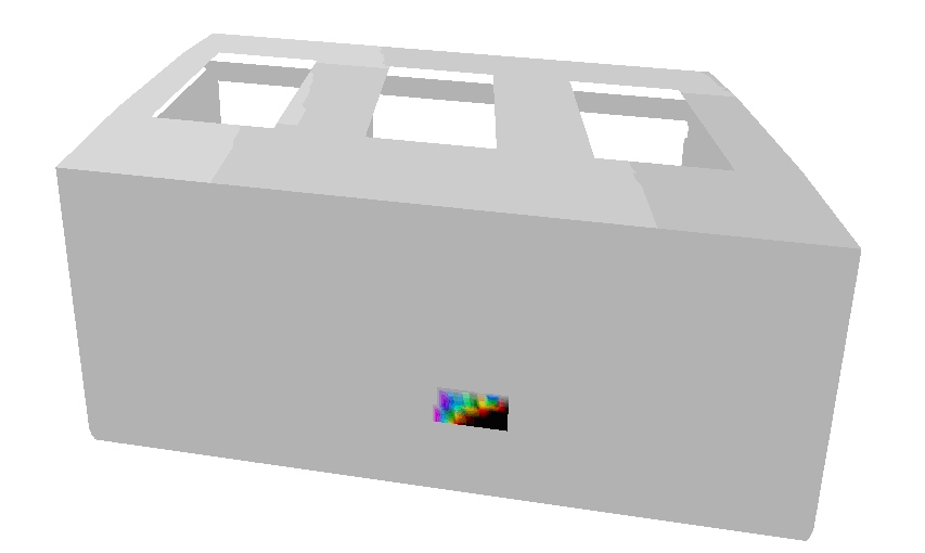
Fig. 7 Distribution of unit pressure on a selected element of the shell plating and its response, in form of structure stress distribution, to this unit pressure
 |
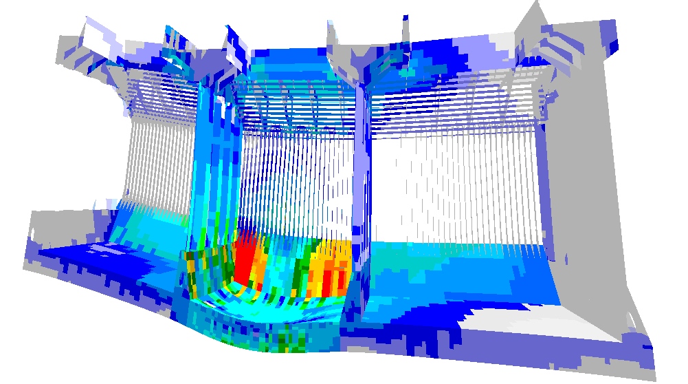 |
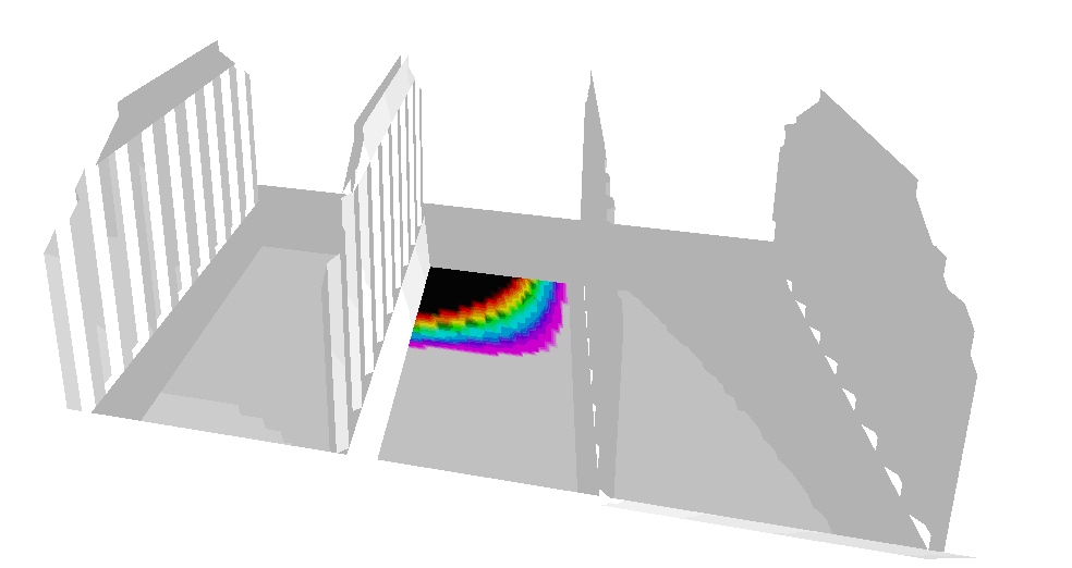
Fig. 8 Distribution of unit pressure in a selected structure element and its impact on stress distribution in the structure
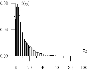
Stress simulation in various sea states provides the option to develop the probability density function of stresses in particular ship structure elements. Sample distributions are shown in the figures below.
 |
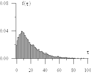 |
Fig. 9 Reduced and tangent stress probability density function in the examined