In the Research and Development Department, studies regarding the impact of the carried low-temperature cargo on the temperature distribution within the hull structural elements were carried out. Currently, LNG (liquified natural gas) is most commonly transported by ships, specially designed for the purpose. Additionally, LNG is becoming more and more popular as an alternative fuel compared to typical heavy fuels, mostly due to the lower carbon dioxide emission. Therefore, the tanks for LNG are mounted more and more frequently in other ship types (mainly Ro-Pax).
The LNG takes a liquified form at a very low temperature of approx. -163 ⁰C. It could trigger various problems related to the ship's hull structural integrity. Although the insulation between the cargo and hull structure is applied, the ship’s hull is still subject to low temperatures. In such situations, conventional hull structural steel may become brittle, increasing its susceptibility to cracking. Additionally, the low temperature causes the shrinking of the steel elements, which could induce the high-stress level in the structure. The solution to that problem is to apply – in regions of low temperature in the hull structure – other grades of steel, with a low temperature of transition to a brittle state and low thermal expansion coefficient.
During the structural design process of LNG ships, the temperature distribution within the hull should be estimated to choose the steel grade properly. One of the methods is to perform analytical computations. However, such calculations can be quite complicated in the case of multiple structural elements surrounding the LNG tanks. Therefore, an alternative method will employ numerical simulations using the Finite Element Method. As part of the research and development works carried out in PRS, both methods were used. The results of both methods have been compared.
An example of temperature distribution in the region of the double bottom of the typical LNG ship is presented in the Figure below:
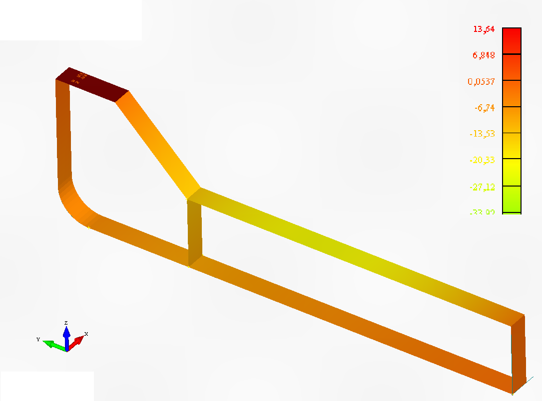
Figure 1. Temperature distribution in the double bottom of LNG ship [⁰C].
The problem of temperature distribution was solved with the assumption that the temperature inside the cargo tank, which is adjacent to the ballast tanks, was equal to -163⁰C. Between the hull structure and tank, an insulation layer was modelled. Two heat transfer mechanisms were included in computations, i.e. convection and conduction [1, 2]. Conduction causes heat transfer inside the steel elements, whereas convection is responsible for the heat transfer inside the ballast tanks. The ballast tanks could be empty or filled with ballast water; in both cases, different thermal properties had to be considered. The thermal properties of steel need to be determined appropriately as well [3]. Where the external hull contacts seawater, the temperature of 0 ⁰C was assumed (acc. to IGC code [4]). The temperature distribution presented in Figure 1 was established based on the computations.
Compared to the analytical method, FE modelling provides results much faster. Additionally, a 3D heat transfer analysis can be carried out (i.e. with consideration of transverse bulkheads).
Based on the carried out works, the guidelines for performing such computations will be developed.
Literature
[1] von Böckh P, Wetzel T. Heat Transfer. Berlin, Heidelberg: Springer Berlin Heidelberg; 2012.
[2] Annaratone D. Engineering Heat Transfer. Berlin, Heidelberg: Springer Berlin Heidelberg; 2010.
[3] Marquardt ED, Le JP, Radebaugh R. Cryogenic Material Properties Database. Cryocoolers 11, Boston, MA: Springer US; 2002, p. 681–7.
[4] International Maritime Organization. International code for the construction and equipment of ships carrying liquefied gases in bulk. London: IMO; 2016.